

To open Workflow Builder:
- On the Workflows page, select the workflow you want to build or edit.
- Select Go to Flow. The flow canvas opens.
Canvas overview
The Workflow Builder canvas is divided into the following areas:
Every new workflow starts with a Start node placed on the canvas automatically. The Start node is the required entry point — all other nodes must connect to it, directly or indirectly.
Manage input and output
Workflows use input and output variables to pass data into and out of the flow. Both are accessible as context objects throughout execution.- Input variables: Provide initial data to the workflow. Available immediately after the Start node.
- Output variables: Store the values returned by the workflow. Define these to capture the results you want to expose.
Use variables in the flow
Access variables using context object syntax:- Input variable:
context.steps.Start.<variableName> - Output variable (to reference an AI node’s result in the End node):
{{context.steps.<NodeName>.output}}
Add input variables
- Select Manage I/O at the top of the canvas, or select the Start node. The Manage Input & Output dialog opens.
- On the Input tab, select + Add input variable.
- Enter a Name (key) for the variable.
-
Select a Type and configure the type-specific options:
- Select Save.
Add output variables
- Select Manage I/O at the top of the canvas. The Manage Input & Output dialog opens.
- On the Output tab, select + Add output variable.
- Enter a Name (key) for the variable.
- Select a Type: String, Number, JSON, or Boolean.
- Select Save.
If a type mismatch occurs between the defined output variable type and the actual value, the endpoint still succeeds but includes a warning in the response with the key name and the nature of the mismatch.
JSON schema format
Use the following format when defining a JSON input variable schema:- Set
type: "object"at the root and add apropertiesobject to define all fields. - For each property, set
typeanddescription. Supported types:string,number,boolean,array,object. For arrays, useitemsto define the element type. - Add a
requiredarray at each level to list all mandatory fields. - Use
enumto restrict a property to a fixed set of values.
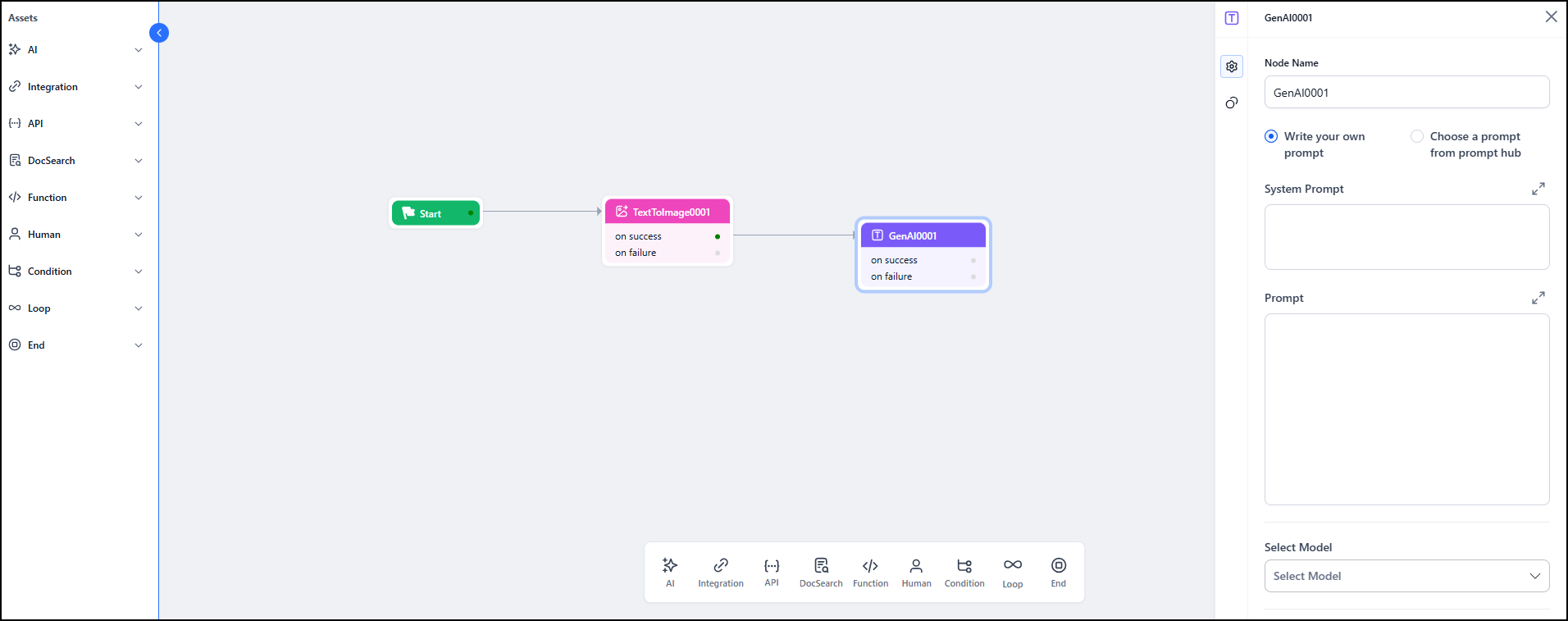
Add nodes
You can add nodes to the canvas in three ways:- Drag from the Assets panel: Scroll the left panel, find the node type, and drag it onto the canvas.
- Use the blue plus (+) icon on a node: Hover over any node to reveal the blue + icon. Select it to add a new node directly connected to the current one, or pick an existing node from the canvas.
- Use the bottom panel: Browse node types in the panel at the bottom of the canvas and drag them onto the canvas.
Connect nodes
Connections between nodes define execution order. Workflow Builder supports two execution patterns:Create a sequential connection
Option 1 — Drag to connect- Hover over the blue
+icon or grey connector dot on the source node. - Drag a line to the destination node.
- Select a node to open the Configuration panel.
- Go to the Connections tab.
- Under On Success or On Failure, select a node from the dropdown. The connection is created and reflected on the canvas.
In a sequential flow, only one connection is allowed per outcome (On Success or On Failure). A second connection from the same outcome creates a parallel branch.
Create a parallel connection
Option 1 — Use the blue + icon- Hover over a node and click the blue + icon.
- Select Add new or Add existing to add multiple nodes as parallel branches. Each added node is connected automatically.
- Hover over the blue + icon or grey dot on the source node.
- Drag a line to an additional node on the canvas.
- Repeat to create more parallel branches from the same source.
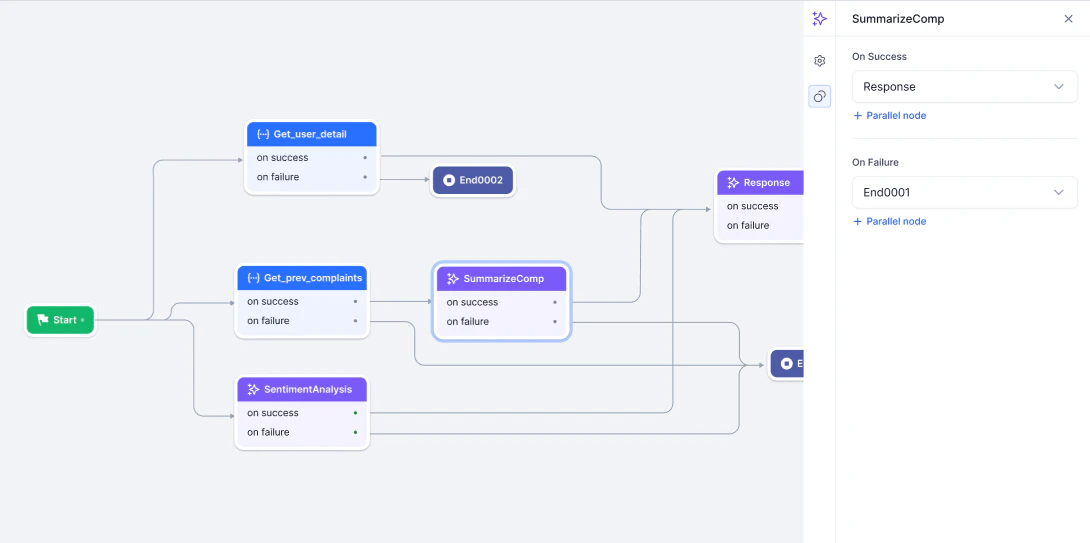
- Select the node to open the Configuration panel.
- Go to the Connections tab.
- Select nodes under On Success or On Failure. Select + Parallel Node to add more branches.
Parallel design patterns
Workflow Builder supports three patterns for parallel execution:
Connection limits and restrictions
- A single node supports up to 10 outgoing connections.
- You cannot connect the same node twice from the same parent.
- Backward connections (looping to a previous node) are not supported.
Rename, rearrange, and delete nodes
Rename a node
- Right-click the node on the canvas.
- Select Rename from the context menu.
- In the Node Name field of the Configuration panel, enter the new name.
Validate Email Input instead of leaving it as the default.
Rearrange nodes
Click and drag a node to any position on the canvas. Connected lines adjust automatically to maintain the connections. Other nodes remain fixed. For automatic layout, right-click anywhere on the canvas and select Auto arrange. You can also toggle canvas display options from the right-click menu: Show/Hide UI or Show/Hide Grid.Delete a node
Right-click the node on the canvas and select Delete. Deleting a node also removes all its connections. Reconnect any dependent paths to keep the flow valid.Manage connections
Delete a connection
- Click the arrow or line between two nodes.
- Select the Delete icon. The nodes remain on the canvas but are no longer linked.
- Select the node to open the Configuration panel.
- In the Connections tab, select the Delete icon next to the connection.
Test a workflow
Use the run feature to test a workflow from the canvas during development.- Select the Run flow icon in the top-right corner of the canvas. The Run dialog opens, showing the Input, Flow log, and Output sections.
- Select the Debug icon at the top of the Run dialog to open the debug log. The debug log shows execution progress as the flow runs.
-
Review the result:
- Successful flow: Execution time and output appear. Select the Copy icon to copy the output.
- Failed flow: An error message appears and the output key is empty.
You can stop the flow at any point and restart it by selecting Run flow again.
Debug log
The debug log provides execution-level detail for each node:
Expand the debug panel to full screen for a cleaner layout. In full-screen mode, clicking any node shows its input, output, and metrics side by side.
Time metrics for API and AI nodes
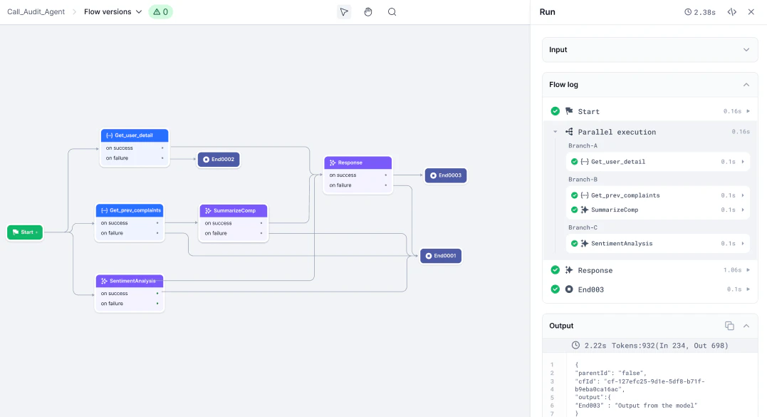
Logs for parallel execution
When a flow includes parallel branches, the debug log groups execution by branch:- Each parallel execution is shown as an indented block under the parent node.
- Branches are labeled (A, B, C) for separate paths.
- Expand or collapse each branch to show or hide its details.
- The workflow waits for all parallel branches to complete before moving to the next step.
Structured response parsing
When an AI node returns a structured JSON response, the platform automatically parses it and stores each key in the node’s context object. Subsequent nodes can reference individual keys directly — no manual parsing or custom code needed.How it works
- Attach a response JSON schema to the AI node to define the expected output structure.
- When the model responds, the platform parses the JSON and stores each key in the node’s context object automatically.
- Access the full output:
{{context.steps.<NodeName>.output}} - Access a specific key:
{{context.steps.<NodeName>.output.<keyName>}}
Example
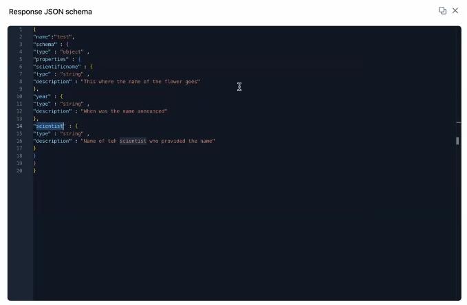
Step 1 — Define the response schema In the AI node, attach a response JSON schema. For example, to retrieve the scientific classification of a flower, define keys:scientificname, year, scientist.
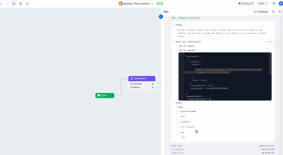
- Input: The prompt sent to the AI node.
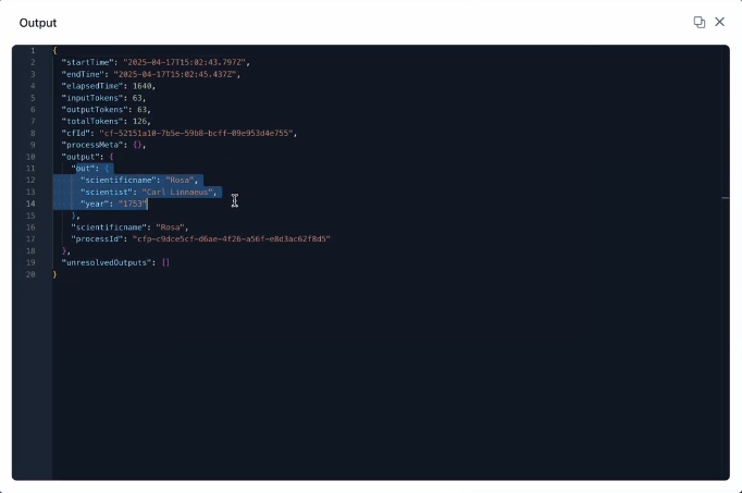
- Response: The structured JSON returned by the model.
- Output: The response split into individual keys based on the defined schema.
{{context.steps.AI0001.output.scientificname}}.
Manage flow versions
You can save named versions of a flow, restore earlier versions, and delete versions you no longer need.Save a version
- Select the down arrow on the canvas header. The Flow versions dialog opens.
- Select the + icon.
- Enter a Version name and Description, then select Save.
Restore or delete a version
In the Flow versions dialog, select the three-dots icon next to any version name to restore or delete it.- Restore: The selected version becomes the current version and moves to the top of the list. The previous current version moves to the bottom. If you edit a restored version, a new current version is created automatically.
- Delete: Permanently removes the version. Deployed versions can be restored but cannot be deleted.
Common issues
Design tips
- Use parallel branches to run independent tasks faster.
- Use sequential paths when each step depends on the previous step’s output.
- Combine both patterns for advanced hybrid flows.
- Use Auto arrange regularly to keep the canvas clean.
- Ensure every logical branch ends at an End node.
- Use the debug log to trace execution and spot bottlenecks.